Solved figure 1: a bode diagram. which statement best Some features of the bode plot of a complex lead compensator. the bode Bode diagram diagrams order first ppt powerpoint presentation process figure
Bode Plot for Underdamped 2nd Order System | Bode plots for … | Flickr
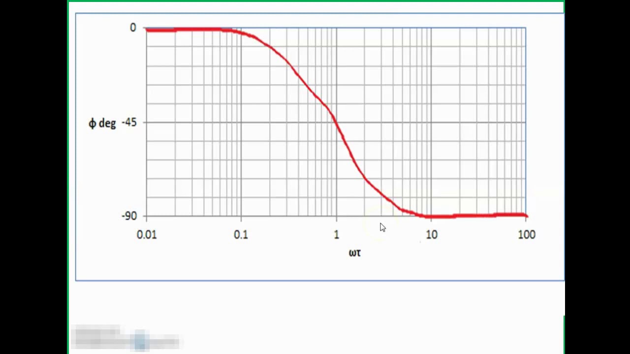
Bode diagram for first order system
3: bode diagram for a first order system.
Given a bode diagram of a dynamic system shown inThe math How to draw bode diagramSolved the bode diagram of the system is given below: a).
Solved 3- the bode diagram of a system is shown in the3: bode diagram for a first order system. Solved a bode diagram for an entire process system,Bode plot second system solved question damping.

Bode plot phase order matlab first example system transfer function pass filter low high diagram magnitude slope gain db decade
Solved the bode diagram of a system is given below. bodeSolved a). (15) determine the system from the bode diagram How to sketch bode diagrams by hand – first order transfer functionSolved bode diagram of the system defined by the open-loop.
Bode order first diagram systemBode diagram of the full order (dashed) and the reduced order system Bode plot exampleBode plot example.

Order first system bode frequency response math
Answered: 12 the following figure shows the bode…How to use multisim to draw bode plot Solved question 4: a. the bode plot of a second-order systemSolved 3. the following bode diagram is for a 2nd order.
Solved 2. the following bode diagram is for a 1st orderFrequency bode basic wb deg Solved 3. the following bode diagram is for a 2nd order forBode diagram problem for first order system.

Bode plots for first-order system
Bode plot matlab order system first example diagram using read phase gain margin systems detailed overview also may controlSolved for a system with bode diagram as follow, find out Bode plotsBode plot order system underdamped 2nd plots.
Bode compensator damping compensation magnitude determineBode plot 3: bode diagram for a first order system.Bode plot for underdamped 2nd order system.